32+ feedback amplifier block diagram
The phase opposition occurs as the amplifier provides 180 o. Notice that the feedback signal is in phase with the input signal.

5 Tone Control Bass Mid Treble Circuits Using Ne5532 4558 Lf353 Electronic Circuit Design Circuit Design Circuit
Search for jobs related to Block diagram of feedback amplifier or hire on the worlds largest freelancing marketplace with 20m jobs.

. Negative feedback in an amplifier is the method of feeding a portion of the amplified output to the input but in opposite phase. FEEDBACK AMPLIFIER BASICS 3 El-a Cts 6. Figure 432 shows a shunt-feedback cascode amplifier with current-source load modeled in Fig.
A block diagram of Blacks basic. The figure below shows negative feedback. Ahmad El-Banna Benha University Faculty of Engineering at Shoubra 16 ECE-322 Electronic Circuits A El-a.
First i c2 must flow through R 2. Its free to sign up and bid on jobs. Figure 211 illustrates the use of equivalences to reduce the block diagram of the common-emitter amplifier previously shown as Figure 27c.
The figure below shows a block diagram of an amplifier with positive feedback. In this feedback the output current io returning to the input as Introducing Ask an Expert We. Concept of Sampling and Comparator Network in Feedback Amplifier.
Feedback amplifiers current series feedback block diagram of feedback is shown in fig. If the magnitude of the input signal is. Notice that there are three stages within the operational amplifier.
Figure below is a block diagram of an operational amplifier. Block diagram of an operational amplifier. Chapter 32 Oscillators Basics of Feedback Block diagram.
Feedback is said to exist in an amplifier circuit when a fraction of the output signal is returned or fed back to the input and combined with the input signal. DMCA Copyright Policy. FEEDBACK AMPLIFIER BLOCK DIAGRAM FABDPDF-118 32 Page File Size 1684 KB 1 Jan 2021 TABLE OF CONTENT Introduction Brief Description Main Topic Technical Note Appendix.
Figure 211a is identical to. A Negative-feedback amplifier or feedback amplifier is an electronic amplifier that subtracts a fraction of its output from its input so that negative fee.

Simple Cost Effective Darlington Amplifier Hifi Amplifier Audio Amplifier Amplifier

5 Tone Control Bass Mid Treble Circuits Using Ne5532 4558 Lf353 Audio Amplifier Circuit Circuit Diagram

Mosfet Amplifier 20watt Output Power Audio Amplifier Electronics Circuit Electronic Circuit Projects

Telephone Amplifier Circuit Diagram Circuit Diagram Electronics Circuit Circuit

Darlington Transistor Tip147 Tip142 Amplifier Circuit Schematic Electronics Projects Amplifier Audio Amplifier Electronic Circuit Design

Mosfet Audio Amplifier Circuit 10 Watt Electronic Circuit Collection Audio Amplifier Electronics Circuit Circuit Diagram

Swahiliteknolojia 30 Watt Audio Power Amplifier Schematic Including Power Amplifiers Audio Amplifier Circuit Diagram

An Audio Power Amp Design That Combines Vacuum Tube Input Circuitry With Solid State Output And Feedback Compo Vacuum Tube Power Amplifiers Electronics Circuit

Elektronika Panosundaki Pin

Operational Amplifier Op Amp Inverting Amplifier Non Inverting Op Amp Amplifier Voltage Divider Amp

Mosfet Linear Amplifier 300w 50mhz Amplifier Linear Circuit Design

Pin Na Doske Amplificatori

Circuit Diagram Of Automatic Gain Control With Microphone And Headset Connections Circuit Design Circuit Electronics Circuit

Isolated Feedback Smps 5vdc 1 5a Power Supply Circuits Power Supply Circuit Circuit Design Electronics Circuit
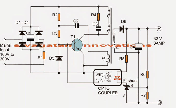
32v 3 Amp Led Driver Smps Circuit Homemade Circuit Projects
Positive And Negative Feedback In Op Amps Circuits Positive And Negative Circuit Simple Circuit

Simple Cost Effective Darlington Amplifier Amplifier Audio Amplifier Electronic Circuit Projects